.png)
Hatching and colors in construction drawings
Basic principles for the representation of cut surfaces and of building materials in construction drawings are contained primarily in the standard sheets DIN ISO 128-50, DIN 1356 and DIN 919.
Marking of cut surfaces
Cut surfaces of building components must be specially highlighted compared to surfaces in elevation drawings.
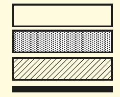
The general marking can be done by
a wide outline around the cut surface,
creation of the surface with a gray point grid,
a simple hatching at 45° to the reading direction,
blackening, especially for narrow cut surfaces.
When hatching, the spacing of the hatching lines must be adapted to the size of the cut surface. If the cut surfaces of two components border on each other, the hatching direction must be changed and, if necessary, the distance between the hatching lines must be altered. If the cut surfaces are blackened, they must be separated from each other by spaces. If dimensions or notes are entered in the cut surface, the hatching shall be interrupted at this point.
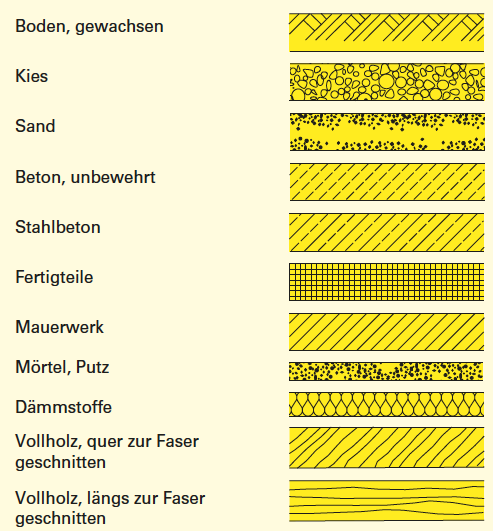
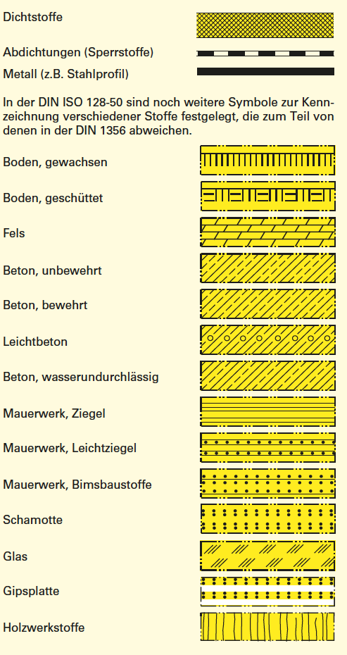
Marking of building materials
Instead of the general marking of cut surfaces, the building materials to be used for the components can be indicated by symbols in accordance with DIN 1356.
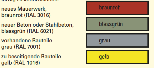
Color coding
In design, execution and part drawings, the components and building materials are usually represented only by black and white hatching. However, according to the Building Documents Ordinance, certain sections and floor plans in the building documents must be color-coded when submitting a building application.
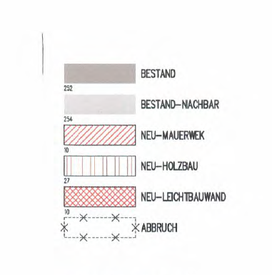
Grey walls or black walls are existing walls
Light grey wall is next-to-building walls
Red hatch wall is new wall from brick
Red vertical hatch wall is new wall made of wood
Squared hatch wall in red is wall made out of plasterboard wall
Dashed contour wall with yellow filling is demolished wall
In principle, hatchings and their outlines must consist of closed polylines. The specifications in the section on surface representations must be observed.
Hatchings composed of complex individual elements or symbols are not permitted. All hatching patterns to be used must be selected in advance on the basis of the CAD test together with the person responsible for CAD.
If possible, the hatching must be editable as a geometric block (associative hatching).
The hatchings are to be stored on the layers provided for this purpose.
The use of SOLID fillings is to be checked via the CAD test with the person responsible for CAD.